Ex6_3:用紅外線遙控MeArm[2]
Ted Lee@
CAVEDU
Jan. 1, 2016

[4]
本文將介紹常見的家電紅外線遙控器來操作MeArm用四顆伺服馬達來模機器擬四軸機器手臂的動作。我們採用各個撃破演算法將題目拆解成兩大塊:紅外線搖控處理(Lab6_3_1)與MeArm操作,再搭配三個實驗(Lab6_3_1-3)來細細品甞Arduino在自動控制上的威力!
本範例过関後,可獲得紅外線控制卡一張。
難易度:中
紅外線(Infrared)簡稱IR,是波長
0.75-1000mm的
電磁波。它的應用方式為
發送器(transmitter)發射紅外線電波信号(signal),
接收器(receiver)接收到此信號後進行解碼(decoding)以控制它对應的電器裝置(devices),如家電用品(如冷氣、音響…)、電腦週邊裝置(如無線滑鼠、鍵盤…)都配有紅外線遙控器供我們
遠控(remote control)操作。
以下的3個實驗Lab6_1-3將使用家電中常見的紅外線遙控器來控制MeArm以4顆伺服馬達(servo motors),用以模擬機器人手臂(robotic arms)的四軸運動。
材料:
- 紅外線遙控器一支
- 38kHz紅外線接收器(例如:TSOP38238、TSOP2438、TSOP4438、PNA4602、FM6038TH2、FM8038TM25DN)一顆
- MeArm一台
- 杜邦線若干條
- 麵包板一塊
- Arduino Uno R3一塊
- A-B型USB傳輸線一條
Lab6_3_1:拆解版(紅外線遙控器內建的通信協定能被IRremote函式庫正確识別)
Lab6_3_2:速配版(紅外線遙控器內建的通信協定能被IRremote函式庫正確识別+按鍵正確解碼)
Lab6_3_3:不知是何姓名版(無法识別遙控器)
Windows:My Documents\Arduino\libraries\
Mac:Documents/Arduino/libraries
Linux:sketchbook內的libraries資料夾
Lab6_3_1:拆解版
程式碼:
#include <IRremote.h>
int RECV_PIN = 2; //使用數位腳位2接收紅外線訊號
IRrecv irrecv(RECV_PIN); //初始化紅外線訊號輸入[3]
decode_results results; //儲存訊號的結構
void setup() {
Serial.begin(9600);
irrecv.blink13(true); //設為true的話,當收到訊號時,腳位13的LED便會閃爍
irrecv.enableIRIn(); //啟動接收
}
void loop() {
if (irrecv.decode(&results)) { //接收紅外線訊號並解碼
Serial.print("results value is "); //輸出解碼後的資料
Serial.print(results.value, HEX);
Serial.print(", bits is ");
Serial.print(results.bits);
Serial.print(", decode_type is ");
Serial.println(results.decode_type);
irrecv.resume(); //準備接收下一個訊號
}
}
Lab6_3_2:速配版
接線图:(
.fzz)

程式流程图如下(
.vsdx):

不同遙控器的按鍵內碼需修改switch中各方向控制的case选項。
#include <Servo.h>
#include <SoftwareSerial.h>
#include <IRremote.h>

const int irReceiverPin = 2; //紅外線接收器輸入訊號接在Arduino第2腳
IRrecv irrecv(irReceiverPin); //宣告IRrecv物件來接收紅外線訊號
decode_results results;

Servo servo_0, servo_1, servo_2, servo_3;

int i0 = 110;
int i1 = 150;
int i2 = 110;
int i3 = 130;
int i0max = 180;
int i0min = 0;
int i1max = 180;
int i1min = 90;
int i2max = 150;
int i2min = 50;
int i3max = 160;
int i3min = 100;

void setup() {
  Serial.begin(9600);
  irrecv.enableIRIn();
  delay(100); //等候信号穩定

  servo_0.attach(11); //buttom
  servo_0.write(i0);

  servo_1.attach(10); //right(面对爪子)
  servo_1.write(i1);

  servo_2.attach(9); //left
  servo_2.write(i2);

  servo_3.attach(5); //claw
  servo_3.write(i3);

  delay(100); //等候信號穩定
} //end of setup()

void loop() {
  if (irrecv.decode(&results)) {
    if (results.value != -1) {
      showIRProtocol(&results);   //顯示紅外線協定的種類
      Serial.println(results.value, HEX);

      switch (results.value) {
        case 0x38863BF8: //前進
          Serial.println("0x2F0:forward");

          if (i2 < i2max) i2++;
          break;
        case 0x38863BC4: //左轉
          Serial.println("0x2D0:turn left");

          if (i0 > i0min) i0++;
          break;
        case 0x38863BE4: //右轉
          Serial.println("0xCD0:turn right");

          if (i0 > i0min) i0--;
          break;
        case 0x38863BC8: //後退
          Serial.println("0xAF0:back");

          if (i2 >= i2min) i2--;
          break;
        case 0x38863BE8: //上移
          Serial.println("0x90:up");

          if (i1 < i1max) i1++;
          break;
        case 0x38863BD8: //下移
          Serial.println("0x890:down");

          if (i1 > i1min) i1--;
          break;
        case 0x38863BE0: //夾緊
          Serial.println("0x490:tight");

          if (i3 < i3max) i3++;
          break;
        case 0x38863BD0: //放鬆
          Serial.println("0xC90:loose");

          if (i3 > i3min) i3--;
          break;
      }//end of switch
    }//end of if

    irrecv.resume(); //Receive the next value

    servo_0.write(i0); //設定四軸初始的転角
    servo_1.write(i1);
    servo_2.write(i2);
    servo_3.write(i3);

    Serial.print("i0 pos ="); //顯示四軸的転角pos
    Serial.println(i0);
    Serial.print("i1 pos =");
    Serial.println(i1);
    Serial.print("i2 pos =");
    Serial.println(i2);
    Serial.print("i3 pos =");
    Serial.println(i3);
    delay(10); //等候信号穩定

    Serial.flush();
  } //end of if
} //end of loop()

void showIRProtocol(decode_results *results) {
  Serial.print("Protocol: ");

  //判斷紅外線協定種類
  switch (results->decode_type) {
    case NEC:
      Serial.print("NEC");
      break;
    case SONY:
      Serial.print("SONY");
      break;
    case RC5:
      Serial.print("RC5");
      break;
    case RC6:
      Serial.print("RC6");
      break;
    default:
      Serial.print("Unknown encoding");
  } //end of switch()

  //把紅外線編碼印到 Serial port
  Serial.print(", irCode: ");
  Serial.print(results->value, HEX);    // 紅外線編碼
  Serial.print(",  bits: ");
  Serial.println(results->bits);        // 紅外線編碼位元數
} //end of showIRProtocol()
以下為加上行号(line number)的程式碼,用以和流程圖相对照,並增進程式撰寫逻輯有更一步了解:
#include <Servo.h>
#include <SoftwareSerial.h>
#include <IRremote.h>
const int irReceiverPin = 2; //紅外線接收器輸入訊號接在Arduino第2腳
IRrecv irrecv(irReceiverPin); //宣告IRrecv物件來接收紅外線訊號
decode_results results;
Servo servo_0, servo_1, servo_2, servo_3;
int i0 = 110;
int i1 = 150;
int i2 = 110;
int i3 = 130;
int i0max = 180;
int i0min = 0;
int i1max = 180;
int i1min = 90;
int i2max = 150;
int i2min = 50;
int i3max = 160;
int i3min = 100;
void setup() {
Serial.begin(9600);
irrecv.enableIRIn();
delay(100); //等候信号穩定
servo_0.attach(11); //buttom
servo_0.write(i0);
servo_1.attach(10); //right(面对爪子)
servo_1.write(i1);
servo_2.attach(9); //left
servo_2.write(i2);
servo_3.attach(5); //claw
servo_3.write(i3);
delay(100); //等候信號穩定
} //end of setup()
void loop() {
if (irrecv.decode(&results)) {
if (results.value != -1) {
showIRProtocol(&results); //顯示紅外線協定的種類
Serial.println(results.value, HEX);
switch (results.value) {
case 0x38863BF8: //前進
Serial.println("0x2F0:forward");
if (i2 < i2max) i2++;
break;
case 0x38863BC4: //左轉
Serial.println("0x2D0:turn left");
if (i0 > i0min) i0++;
break;
case 0x38863BE4: //右轉
Serial.println("0xCD0:turn right");
if (i0 > i0min) i0--;
break;
case 0x38863BC8: //後退
Serial.println("0xAF0:back");
if (i2 >= i2min) i2--;
break;
case 0x38863BE8: //上移
Serial.println("0x90:up");
if (i1 < i1max) i1++;
break;
case 0x38863BD8: //下移
Serial.println("0x890:down");
if (i1 > i1min) i1--;
break;
case 0x38863BE0: //夾緊
Serial.println("0x490:tight");
if (i3 < i3max) i3++;
break;
case 0x38863BD0: //放鬆
Serial.println("0xC90:loose");
if (i3 > i3min) i3--;
break;
}//end of switch
}//end of if
irrecv.resume(); //Receive the next value
servo_0.write(i0); //設定四軸初始的転角
servo_1.write(i1);
servo_2.write(i2);
servo_3.write(i3);
Serial.print("i0 pos ="); //顯示四軸的転角pos
Serial.println(i0);
Serial.print("i1 pos =");
Serial.println(i1);
Serial.print("i2 pos =");
Serial.println(i2);
Serial.print("i3 pos =");
Serial.println(i3);
delay(10); //等候信号穩定
Serial.flush();
} //end of if
} //end of loop()
void showIRProtocol(decode_results *results) {
Serial.print("Protocol: ");
//判斷紅外線協定種類
switch (results->decode_type) {
case NEC:
Serial.print("NEC");
break;
case SONY:
Serial.print("SONY");
break;
case RC5:
Serial.print("RC5");
break;
case RC6:
Serial.print("RC6");
break;
default:
Serial.print("Unknown encoding");
} //end of switch()
//把紅外線編碼印到 Serial port
Serial.print(", irCode: ");
Serial.print(results->value, HEX); // 紅外線編碼
Serial.print(", bits: ");
Serial.println(results->bits); // 紅外線編碼位元數
} //end of showIRProtocol()
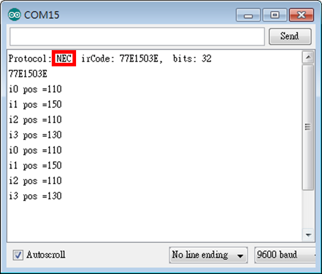
程式的執行畫面為:


Lab6_3_3:不知是何姓名版
基於Lab6_3_2需要相互「速配」才能蹦出火花(在Arduino IDE的串列顯示器上僅會顯示
Unknown encoding),我們找了Epson投影机搖控器
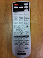
來測試,程式修改處如粉紅色标示處,我們拿到了遙控器识別的副程式showIRProtocol(),並逐一將按鍵的內碼填到方向控制的switch选項內(例如:0xC1AA09F6表示前進)。
程式碼:
#include <Servo.h>
#include <SoftwareSerial.h>
#include <IRremote.h>
const int irReceiverPin = 2; //紅外線接收器輸入訊號接在Arduino第2腳
IRrecv irrecv(irReceiverPin); //宣告IRrecv物件來接收紅外線訊號
decode_results results;
Servo servo_0, servo_1, servo_2, servo_3;
int i0 = 110;
int i1 = 150;
int i2 = 110;
int i3 = 130;
int i0max = 180;
int i0min = 0;
int i1max = 180;
int i1min = 90;
int i2max = 150;
int i2min = 50;
int i3max = 160;
int i3min = 100;
void setup() {
Serial.begin(9600);
irrecv.enableIRIn();
delay(100);
servo_0.attach(11); //buttom
servo_0.write(i0);
servo_1.attach(10); //right(面对爪子)
servo_1.write(i1);
servo_2.attach(9); //left
servo_2.write(i2);
servo_3.attach(5); //claw
servo_3.write(i3);
delay(100);
} //end of setup()
void loop() {
if (irrecv.decode(&results)) {
Serial.print("Key code=");
Serial.println(results.value, HEX);
switch (results.value) {
case 0xC1AA09F6: //前進
Serial.println("0xC1AA09F6:forward");
if (i2 < i2max) i2++;
break;
case 0x38863BC4: //左轉
Serial.println("0x2D0:turn left");
if (i0 > i0min) i0++;
break;
case 0x38863BE4: //右轉
Serial.println("0xCD0:turn right");
if (i0 > i0min) i0--;
break;
case 0x38863BC8: //後退
Serial.println("0xAF0:back");
if (i2 >= i2min) i2--;
break;
case 0x38863BE8: //上移
Serial.println("0x90:up");
if (i1 < i1max) i1++;
break;
case 0x38863BD8: //下移
Serial.println("0x890:down");
if (i1 > i1min) i1--;
break;
case 0x38863BE0: //夾緊
Serial.println("0x490:tight");
if (i3 < i3max) i3++;
break;
case 0x38863BD0: //放鬆
Serial.println("0xC90:loose");
if (i3 > i3min) i3--;
break;
}//end of switch
irrecv.resume(); //Receive the next value
servo_0.write(i0);
servo_1.write(i1);
servo_2.write(i2);
servo_3.write(i3);
Serial.print("i0 pos =");
Serial.println(i0);
Serial.print("i1 pos =");
Serial.println(i1);
Serial.print("i2 pos =");
Serial.println(i2);
Serial.print("i3 pos =");
Serial.println(i3);
delay(10);
Serial.flush();
} //end of if
} //end of loop()
執行結果:
Key code=C1AA09F6
0xC1AA09F6:forward
i0 pos =110
i1 pos =150
i2 pos =110
3 pos =130
Key code=C1AA31CE
i0 pos =110
i1 pos =150
i2 pos =110
i3 pos =130
Key code=C1AA29D6
i0 pos =110
i1 pos =150
i2 pos =110
i3 pos =130
Key code=C1AA0EF1
i0 pos =110
i1 pos =150
i2 pos =110
i3 pos =130
Key code=C1AA6E91
i0 pos =110
i1 pos =150
i2 pos =110
i3 pos =130
Key code=C1AA2ED1
i0 pos =110
i1 pos =150
i2 pos =110
i3 pos =130
Key code=C1AAFC03
i0 pos =110
i1 pos =150
i2 pos =110
i3 pos =130
Key code=C1AAC23D
i0 pos =110
i1 pos =150
i2 pos =110
i3 pos =130
参考資料:
- Arduino練習:紅外線傳送與接收,葉難,http://yehnan.blogspot.tw/2013/05/arduino.html。
- A Multi-Protocol Infrared Remote Library for the Arduino,Ken Shirriff,http://www.righto.com/2009/08/multi-protocol-infrared-remote-library.html.
- IRrecv Class,CY's Tech Talk,http://tech.cyborg5.com/irlib/docs/1-irlib-reference/1-1-receiver-classes/1-1-3-irrecv-class/.
- 六種授權條款,台灣創用CC計畫,http://creativecommons.tw/explore。