2016年3月13日 星期日

[7688 Duo] 7688 Duo有趣的專案及參考資料@Ted好玩


7688 Duo有趣的專案及參考資料
Ted Lee@Ted好玩
May 4, 2016
88x31.png[1]

参考資料:
  1. 六種授權條款

[7688 Duo] DHTXX實測

  • Conclusions:
    • https://www.facebook.com/groups/makerpro.cc/permalink/973163109444410/?comment_id=973311472762907&reply_comment_id=974200559340665&notif_t=group_comment
    • https://labs.mediatek.com/forums/posts/list/4081.page
  • You can't read 1wire device through such platform easily ....its timing issue, better use a i2c version of Dht , I.e. Am2320 ....
    • https://www.facebook.com/groups/makerpro.cc/permalink/965615530199168/?comment_id=965616790199042&ref=notif&notif_t=group_comment
    •  用MTK回覆的cli()和sei()成功解掉了!
  • 有人用 Duo成功把PM2.5及溫溼感測器接上MCS了所以7688是可以接sensors?!
    • https://github.com/future/Linkit7688_PM2.5
  • DHTx:讀取sensoring data要靠S/W
    SHT2X:屬I2C(inter-IC)伝輸,有H/W clock來處理資料同步問題
    我的理解是這樣


    [7688 Duo] 教學經驗分享

    • 原廠手冊(developer guide, FAQ…)及各大communities目前的文章还欠缺7688 Duo送data到cloud(MCS, AWS…)的各類型sample code。例如:MTMega32U從DHT22收到溫溼度值透过UART送給MT7688AN,再傳至MCS顯示,MT7688AN開發手冊就沒有這段的sample code(还停在MT7688AN控LED的階段)
    • MTK在開發手冊中promises會提供Python及Node.js兩套code,不过目前尚未有大幅更新
    • 上Duo講解sensors<->ATMeg32U4<->(UART, Firmata, Yun bridge)MT7688AN<->MSC時速度要放慢一些,學員需要時間理解
      可对照developer guide的MCS控LED及sensors送MCS兩範例詳加舉例
    • 1.win 10裝usb drv因未signed,要手動停用才能裝
      2.有一人換了兩機Arduino IDE一直無法update到出現duo選項
      • 更新BIOS就解掉了,他說他是把DUO接在USB 3.0上
    • 1.有2人自備7688,結果⋯(who am I?),現場有1x個ssid,未曾生我,誰是我?
      建議阿吉請mtk在pcb時加印Mac addr
      2.有1台裝win 10,下課前都抓不到ssid,可能是os或無線網卡問題,有拿其他work的7688接測過
      3.有1台裝ubuntu,ssid重開機才抓得到
      4.用node.js控led時,程式執行前,led一直亮著是正常的(一直亮還有2種狀況:booting、f/w error)
      5.mcs的LED_Contol容易沒設正確
      6.抓SSID和MCS設定學習比較容易突搥

    [7688 Duo] 支援的webcam實測報告


    • Not support:

    2016年3月6日 星期日

    [Arduino] Ex1_3:紅錄燈控制

    Ex1_3:紅錄燈控制
    Ted Lee@CAVEDU
    Mar. 6, 2016
    88x31.png[1]

    本實驗延伸Ex1_1的Lab1_1_2,將LED的正極由原先接到Arduino第13腳改接到第9腳,並將程式由呼叫digitalWrite()改為呼叫analogWrite()。因為analogWrite()使用變更工作週期(duty cycle)PWM技術來模擬連續性的類比信号,故能使LED亮度而有漸明/暗的效果,也就是常聽到呼吸灯的由來。

    本範例过関後,可獲得LED灯光Fade卡一張。

    難易度:易

    材料
    1. LED(Light-Emitting Diode,發光二極体)一顆
    2. 220W電阻一顆(色环:紅紅棕金)
    3. 杜邦線2條
    4. 麵包板一塊
    5. Arduino Uno R3一塊(本系列文章皆簡稱為Arduino開發版
    6. A-B型USB傳輸線一條

    程式Fade.ino
    在Arduino IDE中由Fade File->Examples->1.Basics->Fade開啟Arduino內建的範例程式。
    int brightness = 0;    // how bright the LED is
    int fadeAmount = 5;    // how many points to fade the LED by
    void setup()  {   
      // declare pin 9 to be an output:   
      pinMode(9, OUTPUT);
    } 
    void loop()  {   
      // set the brightness of pin 9:   
      analogWrite(9, brightness);  
      // change the brightness for next time through the loop:   
      brightness = brightness + fadeAmount;  
      // reverse the direction of the fading at the ends of the fade:   
      if (brightness == 0 || brightness == 255){   
        fadeAmount = -fadeAmount ;   
      }       
      delay(30); // wait for 30 milliseconds to see the dimming effect    
    }
    流程圖.vsdx
    執行結果
    接線圖.fzz
    高手必練
    修改控制LED明滅度fadeAmount的值(例如:5->10),再覌察LED灯的明滅是否有不同變化

    2016年2月22日 星期一

    [IoT] 歺飲IoT


    請舉出一部IoT應用至餐飲業的影片,以留言的方式寫下:
    1. 學号
    2. 姓名
    3. 搜尋関鍵字
    4. 影片名稱
    5. 影片連結
    6. 影片內容簡介
    P.S.留言以先交先贏方式採計:若搜尋到相同的影片,以先PO者勝之!

    2016年2月12日 星期五

    [7688 Duo] 一閃一閃亮晶晶(Blink)

    一閃一閃亮晶晶(Blink)
    Ted Lee@CAVEDU
    Feb. 12, 2016
    88x31.png[1]

    本實驗延伸Ex1_1的Lab1_1_2,將LED的正極由原先接到Arduino第13腳改接到第9腳,並將程式由呼叫digitalWrite()改為呼叫analogWrite()。因為analogWrite()使用變更工作週期(duty cycle)PWM技術來模擬連續性的類比信号,故能使LED亮度而有漸明/暗的效果,也就是常聽到呼吸灯的由來。

    本範例过関後,可獲得LED灯光Fade卡一張。

    難易度:易

    材料
    1. LED(Light-Emitting Diode,發光二極体)一顆
    2. 220W電阻一顆(色环:紅紅棕金)
    3. 杜邦線2條
    4. 麵包板一塊
    5. Arduino Uno R3一塊(本系列文章皆簡稱為Arduino開發版
    6. A-B型USB傳輸線一條

    程式Fade.ino
    在Arduino IDE中由Fade File->Examples->1.Basics->Fade開啟Arduino內建的範例程式。
    int brightness = 0;    // how bright the LED is
    int fadeAmount = 5;    // how many points to fade the LED by
    void setup()  {   
      // declare pin 9 to be an output:   
      pinMode(9, OUTPUT);
    } 
    void loop()  {   
      // set the brightness of pin 9:   
      analogWrite(9, brightness);  
      // change the brightness for next time through the loop:   
      brightness = brightness + fadeAmount;  
      // reverse the direction of the fading at the ends of the fade:   
      if (brightness == 0 || brightness == 255){   
        fadeAmount = -fadeAmount ;   
      }       
      delay(30); // wait for 30 milliseconds to see the dimming effect    
    }
    流程圖.vsdx
    執行結果
    接線圖.fzz
    高手必練
    修改控制LED明滅度fadeAmount的值(例如:5->10),再覌察LED灯的明滅是否有不同變化

    2016年1月31日 星期日

    [7688 Duo] Station mode補完:Win 7下連外網

    Station mode補完:更改Device name就能在Win 7下連外網
    Ted Lee@CAVEDU
    Jan. 31, 2016
    88x31.png[1]

    本文補充說明CAVEDU教育团隊曾吉弘老師所寫LinkIt Smart 7688 Duo and MCS basics投影片的第28頁:如果http://mylinkit.local連不上怎麼辨?
    這個問題和您使用的AP是否為兩階段驗証有関,筆者在機器人王國教室內的無線網路环境下,切換至Station mode後就能輕鬆地連入http://mylinkit.local。總之,兩階段驗証的AP不OK啦!Crying…

    我們的開發环境為:
    • H/W:
      • CPU:i7-4510U@2GHz 2.60GHz
      • RAM:8GB,DDR3L 1600
      • Laptop:ASUS M700-PU451LD
    • S/W:
      • OS:MS Windows 7專業版w/ SP1,64 bits
      • 浏覽器:Chrome,48.0.2564.97 m
    • 開發版:LinkIt Smart 7688 Duo(以下簡稱7688D),F/W版本:0.9.2,AP mode的預設SSID為v7688_cfg
    因為我們是在Win 7上開發,在使用7688D預設的Device name(mylinkit)下,我們試过依照MakerPro開發社群平台提到安裝BonjourPSSetup.exe的方法,卻裝不起該services。好在有CAVEDU教育团隊曾吉弘及徐丰智兩位大師鼎力協助才得以順利完成,在此謝过啰~。

    設定步驟如下:
    1. 切換至AP mode 有兩种切換的方法:第一、長按WiFi按鈕5秒;第二、晶片reset:長按WiFi按鈕20秒。
    2. 和7688D連線 
    3. 更改Device name 以英文字母的大、小寫+數字重新命名,例如:TedLee7688d。這是最関鍵的步驟!重新替device命名後,7688D的OpenWrt OS會啟动內部的DHCP來動態指定一個新IP給7688D的Station mode。
    4. 將電腦連至外網 选擇非兩階段驗証的AP,或者以英文命名的手機熱奌(hot spot)
    5. 在浏覽器上以http://新Device name.local/重新連入7688D 
    6. 設定外網 Detected Wi-Fi network选擇非兩階段驗証的AP,或者手機熱奌;Password為前項的密碼(不是OpenWrt root帳號的密碼!)。
    7.  新Device name已取得新IP 

    参考資料:
    1. 六種授權條款

    2016年1月13日 星期三

    [Arduino] 使用Autodesk 的123D Circuits來玩Arduino

    使用Autodesk 的123D Circuits來玩Arduino
    Ted Lee@CAVEDU
    Jan. 10, 2016
    88x31.png[1]

    本文將介紹
    常見的家電紅外線遙控器來操作MeArm用四顆伺服馬達來模機器擬四軸機器手臂的動作。我們採用各個撃破演算法將題目拆解成兩大塊:紅外線搖控處理(Lab6_3_1)與MeArm操作,再搭配三個實驗(Lab6_3_1-3)來細細品甞Arduino在自動控制上的威力!
    本範例过関後,可獲得LED灯光Fade卡一張。

    難易度:易

    材料:
    1. LED(Light-Emitting Diode,發光二極体)一顆
    2. 220W電阻一顆(色环:紅紅黑金)
    3. 杜邦線若干條
    4. 麵包板一塊
    5. Arduino Uno R3一塊(本系列文章皆簡稱為Arduino開發版
    6. A-B型USB傳輸線一條

    第一個實驗將以Arduino IDE內建的範例程式集(built-in examples)中的Blink(註一)做為踏入Arduino殿堂的第一支程式,同時也測試一下前面設定了老半天的环境是否可以正確地誏我們開發程式(註二)。
    開啟Blink後的程式碼(註三)為:
    /*
      Blink
      Turns on an LED on for one second, then off for one second, repeatedly.
    
      Most Arduinos have an on-board LED you can control. On the Uno and
      Leonardo, it is attached to digital pin 13. If you're unsure what
      pin the on-board LED is connected to on your Arduino model, check
      the documentation at http://www.arduino.cc
    
      This example code is in the public domain.
    
      modified 8 May 2014
      by Scott Fitzgerald
     */
    
    
    // the setup function runs once when you press reset or power the board
    void setup() {
      // initialize digital pin 13 as an output.
      pinMode(13, OUTPUT);
    }
    
    // the loop function runs over and over again forever
    void loop() {
      digitalWrite(13, HIGH);   // turn the LED on (HIGH is the voltage level)
      delay(1000);              // wait for a second
      digitalWrite(13, LOW);    // turn the LED off by making the voltage LOW
      delay(1000);              // wait for a second
    }
    它对應的程式流程圖為:

    執行結果

    註一:從範例中學習(learning by examples)[1]是學習寫程式(programming)最快的方法之一,筆者強烈推荐!
    註二:大抵上,軟、硬体的專案(project)開發流程為:
    註三:Arduino程式的基本架構(structure)由兩個副程式(subroutines)所組成:
    1. setup():程式執行前的設定(setting),稱之為初始化(initialize),例如:設定串列傳輸速率為9,600bps(bit per second)
    2. loop():不斷重複執行(repeatedly execution)的副程式控制碼(control code),例如:控制馬達不停轉動。
    void setup() {
         
    }
    void loop() {
     
    }

    Lab1_1_2
    接線图接線影片
    執行結果

    参考資料:
    1. 六種授權條款

    2016年1月11日 星期一

    [Makers(創客)] 從想法(Ideas)到作品(Works)的最後一哩路:創客空間(Maker Spaces)急遽加速的綜效

    從想法(Ideas)到作品(Works)的最後一哩路:
    創客空間(Maker Spaces)急遽加速的綜效
    Ted Lee
    Jan. 11, 2016
    88x31.png[1]

    從前,要將心中的想法做成作品,需要先學會某些專業知识、利用某些科技工具,再使用某些造价不斐的機台來達成。
    科技的急遽發展,使得过往只能由少數領域專家(domain experts)所掌控的各類專業知识(domain knowledge)一時之間如水銀瀉地般在虛擬空間(virtual spaces)之中快速的產出與累積。這股驚濤拍岸的浪潮,也正如狂風掃落葉般以迅雷不及掩耳的姿態呼嘯地席捲而來。
    美國最知名的創客空間TechShop的創始人馬克.哈奇(Mark Hatch)在他所著的《全世界在瘋什麼自造者運動?》中分享了數個因為失業而参與TechShop各類短期的課程,以便將他們腦袋中浮現的想法快速地創做出成品的成功案例!這些令人興奮的故事,都說明了創客空間整合了最新穎的科技、融合各領域的專業知识與可快速量產的各式機台正以前所未有態勢縮短作品製造成型的時間。

    参考資料:
    1. 六種授權條款

    2016年1月9日 星期六

    [Arduino] Ex1_2:床頭灯控制(Fade)

    Ex1_2:床頭灯控制(Fade)
    Ted Lee@CAVEDU
    Jan. 9, 2016
    88x31.png[1]

    本實驗延伸Ex1_1的Lab1_1_2,將LED的正極由原先接到Arduino第13腳改接到第9腳,並將程式由呼叫digitalWrite()改為呼叫analogWrite()。因為analogWrite()使用變更工作週期(duty cycle)PWM技術來模擬連續性的類比信号,故能使LED亮度而有漸明/暗的效果,也就是常聽到呼吸灯的由來。

    本範例过関後,可獲得LED灯光Fade卡一張。

    難易度:易

    材料
    1. LED(Light-Emitting Diode,發光二極体)一顆
    2. 220W電阻一顆(色环:紅紅棕金)
    3. 杜邦線2條
    4. 麵包板一塊
    5. Arduino Uno R3一塊(本系列文章皆簡稱為Arduino開發版
    6. A-B型USB傳輸線一條

    程式Fade.ino
    在Arduino IDE中由Fade File->Examples->1.Basics->Fade開啟Arduino內建的範例程式。
    int brightness = 0;    // how bright the LED is
    int fadeAmount = 5;    // how many points to fade the LED by
    void setup()  {   
      // declare pin 9 to be an output:   
      pinMode(9, OUTPUT);
    } 
    void loop()  {   
      // set the brightness of pin 9:   
      analogWrite(9, brightness);  
      // change the brightness for next time through the loop:   
      brightness = brightness + fadeAmount;  
      // reverse the direction of the fading at the ends of the fade:   
      if (brightness == 0 || brightness == 255){   
        fadeAmount = -fadeAmount ;   
      }       
      delay(30); // wait for 30 milliseconds to see the dimming effect    
    }
    流程圖.vsdx
    執行結果
    接線圖.fzz
    高手必練
    修改控制LED明滅度fadeAmount的值(例如:5->10),再覌察LED灯的明滅是否有不同變化

    2016年1月3日 星期日

    [Arduino] 電路迴路(Circuit Loop)

    電路迴路(Circuit Loop)
    Ted Lee@CAVEDU
    Jan. 3, 2016
    88x31.png[1]

    動畫中,任意挑選右邊的三條連接線(wire)將左邊的電池、開関(switch)與灯泡接起來,使得按下開関後灯泡就會奌亮。
    這個動畫闡述了電路迴路(簡稱迴路)的動作原理:接妥線路後,
    開関未按下時電路是不導通
    相反的,按下開関後,電流從電池的正極(+)出發,流向開關、灯泡,再回到電池的負極(-),形成一條封閉的迴路(closed loop),即稱為此電路的迴路。
    這整個过程可以將Loop.txt匯入(import)到Paul Falstad的Circuit Simulator Applet即見分明!

    PS 也可以使用Autodesk出的網頁版(web-based)工具 123D Circuits來玩!
    本概念过関後,可獲得迴路一張。

    参考資料:
    1. 六種授權條款,台灣創用CC計畫,http://creativecommons.tw/explore。


    2016年1月2日 星期六

    [Arduino] Ex1_1:一閃一閃亮晶(Blink)

    Ex1_1:一閃一閃亮晶(Blink)
    Ted Lee@CAVEDU
    Jan. 2, 2016
    88x31.png[3]

    本文從Arduino專案開發前的工作环境建置、測試,引入了毋需接電路(Lab1_1_1)及需另接電路(Lab1_1_2)兩個實驗來引領學員邁進Arduino的神秘殿堂,並援用了Arduino IDE內建範例集中的Blink來介紹Arduino控制程式的基本架構及語法。
    本範例过関後,可獲得LED灯光Blink卡Arduino程式架構卡各一張。

    難易度:易

    材料:
    1. LED(Light-Emitting Diode,發光二極体)一顆
    2. 220W電阻一顆(色环:紅紅棕金)
    3. 杜邦線若干條
    4. 麵包板一塊
    5. Arduino Uno R3一塊(本系列文章皆簡稱為Arduino開發版
    6. A-B型USB傳輸線一條

    Arduino開發环境建置
    1. Arduino的官網(official website)右側选擇與目前電腦中安裝的作業系統(Operating System)相符的版本[2]。
    2. 雙撃(double click)步驟1下載完成的「arduino-1.6.7-windows.exe」進行安裝。
    3. 在安裝的过程也會順帶將開發版的USB驅動程式(driver)一併裝妥。
    4. 选擇要安裝的目錄。
    5. 從File®Preferences中調整Arduino IDE(Integrated Development Environment)环境,設定顯示字型為14、標示程式碼的行号(line number)
    6. 將開發版以A-B型USB連接線串接電腦與開發版。
    7. 設定開發版的型号(board model)通信使用的埠号(port number)

      1. 從功能表Tools的Board: "Arduino/Genuino Uno"选擇我們使用的開發Arduino/Genuino Uno
      2. 設定板子和電腦的通信Port為COMx(編號x會因不同電腦及不同USB埠而配置(allocate)到不同的數值。一般而言,也就是說您和隔壁學員所「抽到」的號碼牌x不會同号,這是正常的情形喔,Don't panic!)。
    8. 將Blink.ino燒錄到開發版上。

    這個範例有兩個實驗:

    Lab1_1_1:奌亮內建(on-board)LED(使用Arduino第13腳內部連接的LED)
    Lab1_1_2:奌亮外接LED(Arduino第13腳串接一限流電阻與LED)

    從以下的Arduino開發版的電路图(schematic diagram)中,可以看到的第13腳(藍框)同時接到LED(綠框)及輸出。所以這兩個實驗都用同一接腳來奌亮LED,控制程式亦為同一支:Blink.ino。


    Lab1_1_1
    第一個實驗將以Arduino IDE內建的範例程式集(built-in examples)中的Blink(註一)做為踏入Arduino殿堂的第一支程式,同時也測試一下前面設定了老半天的环境是否可以正確地誏我們開發程式(註二)。
    開啟Blink後的程式碼(註三)為:
    /*
      Blink
      Turns on an LED on for one second, then off for one second, repeatedly.
    
      Most Arduinos have an on-board LED you can control. On the Uno and
      Leonardo, it is attached to digital pin 13. If you're unsure what
      pin the on-board LED is connected to on your Arduino model, check
      the documentation at http://www.arduino.cc
    
      This example code is in the public domain.
    
      modified 8 May 2014
      by Scott Fitzgerald
     */
    
    
    // the setup function runs once when you press reset or power the board
    void setup() {
      // initialize digital pin 13 as an output.
      pinMode(13, OUTPUT);
    }
    
    // the loop function runs over and over again forever
    void loop() {
      digitalWrite(13, HIGH);   // turn the LED on (HIGH is the voltage level)
      delay(1000);              // wait for a second
      digitalWrite(13, LOW);    // turn the LED off by making the voltage LOW
      delay(1000);              // wait for a second
    }
    

    程式呼叫(invoke)了Arduino內建(built-in)API(Application Programming Interface,應用程式介面)中的三個函式:pinMode()digitalWrite()delay()來完成任務(註四)。

    程式流程圖(flow chart)為:
    /*
      Blink
      Turns on an LED on for one second, then off for one second, repeatedly.
    
      Most Arduinos have an on-board LED you can control. On the Uno and
      Leonardo, it is attached to digital pin 13. If you're unsure what
      pin the on-board LED is connected to on your Arduino model, check
      the documentation at http://www.arduino.cc
    
      This example code is in the public domain.
    
      modified 8 May 2014
      by Scott Fitzgerald
     */
    
    
    // the setup function runs once when you press reset or power the board
    void setup() {
      // initialize digital pin 13 as an output.
      pinMode(13, OUTPUT);
    }
    
    // the loop function runs over and over again forever
    void loop() {
      digitalWrite(13, HIGH);   // turn the LED on (HIGH is the voltage level)
      delay(1000);              // wait for a second
      digitalWrite(13, LOW);    // turn the LED off by making the voltage LOW
      delay(1000);              // wait for a second
    }


    執行結果

    註一:從範例中學習(learning by examples)[1]是學習寫程式(programming)最快的方法之一,筆者強烈推荐!
    註二:大抵上,軟、硬体的專案(project)開發流程為:
    Arduino程式的除錯技巧可参閱使用Autodesk 的123D Circuits來玩Arduino。
    註三:Arduino程式(xxx.ino)的基本架構(structure)由兩個副程式(subroutines)所組成:
    1. setup():程式執行前的設定(setting),稱之為初始化(initialize),例如:設定串列傳輸速率為9,600bps(bit per second)
    2. loop():不斷重複執行(repeatedly execution)的副程式控制碼(control code),例如:控制馬達不停轉動。
    void setup() {
         
    }
    void loop() {
     
    }
    註四:Arduino程式的語法(syntax)類C(C-like)高階程式語言(high-level programming language)。想流暢地駕馭程式創作,需要了解:
    1. 了解Arduino的基本語法 程式語言的語法好比英文的文法(grammar),一定要按照規定的格式(format)表述才能誏呆呆的電腦理解我們要交付的任務,例如:除了特殊指令(像if、while…)外,每條指令都一定要以;表程結尾。
    2. 學會查Arduino API文件 在學習Arduino專案程式開發的过程中,我們必需時時對這個官方提供的API有一定程度的了解:
      • API的架構(structure) 筆者將之分成以下六大類:
        1. I/O(Input/Output,輸入/輸出)
          1. 數位(Digital I/O)
          2. 類比(Analog I/O)
          3. 進階(Advanced I/O)
        2. 時間(Time)
        3. 數學(Math)
          1. 三角函數(Trigonometry)
          2. 乱數(Random Numbers)
        4. 字串(Strings)
          1. 字元(Characters)
          2. 位元(Bits)及位元組(Bytes)
        5. 中斷(Interrupts)
          1. 內部中斷(Internal Interrupts)
          2. 外部中斷(External Interrupts)
        6. 通信(Communication)
      • API函式的功能 例如:digitalWrite()是將高/低電位(HIGH/LOW)值輸出到Arduino開發版。
      • API函式的參數(parameter/argument) 以digitalWrite(pin,value)來說,它使用兩個参數來將value值輸出到Arduino開發版的pin腳位
    Lab1_1_2
    接線图.fzz)及接線影片
    執行結果

    参考資料:
    1. Learning Programming Fast In Just 5 Steps.
    2. Getting Started with Arduino on Windows.
    3. 六種授權條款

    2015年12月26日 星期六

    [Arduino] Ex6_3:用紅外線遙控MeArm

    Ex6_3:用紅外線遙控MeArm[2]
    Ted Lee@CAVEDU
    Jan. 1, 2016
    88x31.png[4]

    本文將介紹常見的家電紅外線遙控器來操作MeArm用四顆伺服馬達來模機器擬四軸機器手臂的動作。我們採用各個撃破演算法將題目拆解成兩大塊:紅外線搖控處理(Lab6_3_1)MeArm操作,再搭配三個實驗(Lab6_3_1-3)來細細品甞Arduino在自動控制上的威力!
    本範例过関後,可獲得紅外線控制卡一張。

    難易度:中

    紅外線(Infrared)簡稱IR,是波長0.75-1000mm電磁波。它的應用方式為發送器(transmitter)發射紅外線電波信号(signal),接收器(receiver)接收到此信號後進行解碼(decoding)以控制它对應的電器裝置(devices),如家電用品(如冷氣、音響…)、電腦週邊裝置(如無線滑鼠、鍵盤…)都配有紅外線遙控器供我們遠控(remote control)操作。
    以下的3個實驗Lab6_1-3將使用家電中常見的紅外線遙控器來控制MeArm以4顆伺服馬達(servo motors),用以模擬機器人手臂(robotic arms)的四軸運動。

    材料:
    1. 紅外線遙控器一支
    2. 38kHz紅外線接收器(例如:TSOP38238、TSOP2438、TSOP4438、PNA4602、FM6038TH2、FM8038TM25DN)一顆
    3. MeArm一台
    4. 杜邦線若干條
    5. 麵包板一塊
    6. Arduino Uno R3一塊
    7. A-B型USB傳輸線一條

    Lab6_3_1:拆解版(紅外線遙控器內建的通信協定能被IRremote函式庫正確识別)
    Lab6_3_2:速配版(紅外線遙控器內建的通信協定能被IRremote函式庫正確识別+按正確解碼)
    Lab6_3_3:不知是何姓名版(無法识別遙控器)

    Lab6_1-3都援用了Ken Shirriff[2]寫的IRremote函式庫,下載後請放到Arduino的函數庫內──若程式編譯時出現和函式庫衝突,請參考葉難的解方(solution)

    Windows:My Documents\Arduino\libraries\
    Mac:Documents/Arduino/libraries
    Linux:sketchbook內的libraries資料夾

    Lab6_3_1:拆解版
    這個實驗使用Mac專用遙控器38kHz紅外線接收器(接腳由左至右依順為Vout, GND, Vcc)。
    程式碼:
    #include <IRremote.h>

    int RECV_PIN = 2;        //使用數位腳位2接收紅外線訊號
    IRrecv irrecv(RECV_PIN); //初始化紅外線訊號輸入[3]
    decode_results results;  //儲存訊號的結構

    void setup() {
      Serial.begin(9600);
      irrecv.blink13(true); //設為true的話,當收到訊號時,腳位13的LED便會閃爍
      irrecv.enableIRIn();  //啟動接收
    }

    void loop() {
      if (irrecv.decode(&results)) {   //接收紅外線訊號並解碼
        Serial.print("results value is "); //輸出解碼後的資料
        Serial.print(results.value, HEX);
        Serial.print(", bits is ");
        Serial.print(results.bits);
        Serial.print(", decode_type is ");
        Serial.println(results.decode_type);
        irrecv.resume(); //準備接收下一個訊號
      }
    }

    Lab6_3_2:速配版
    接線图:(.fzz
    程式流程图如下(.vsdx):
    程式碼:程式撰寫逻輯採演算法的各個撃破(divide and conquer)技巧,共可分為紅外線搖控處理(Lab6_3_1)MeArm操作兩段落,MeArm四軸的伺服馬達基本控制請参考Ex2_1,馬達與程式的對應為
    不同遙控器的按鍵內碼需修改switch中各方向控制的case选項
    #include <Servo.h>
    #include <SoftwareSerial.h>
    #include <IRremote.h>

    const int irReceiverPin = 2; //紅外線接收器輸入訊號接在Arduino第2腳
    IRrecv irrecv(irReceiverPin); //宣告IRrecv物件來接收紅外線訊號
    decode_results results;

    Servo servo_0, servo_1, servo_2, servo_3;

    int i0 = 110;
    int i1 = 150;
    int i2 = 110;
    int i3 = 130;
    int i0max = 180;
    int i0min = 0;
    int i1max = 180;
    int i1min = 90;
    int i2max = 150;
    int i2min = 50;
    int i3max = 160;
    int i3min = 100;

    void setup() {
      Serial.begin(9600);
      irrecv.enableIRIn();
      delay(100); //等候信号穩定

      servo_0.attach(11); //buttom
      servo_0.write(i0);

      servo_1.attach(10); //right(面对爪子)
      servo_1.write(i1);

      servo_2.attach(9); //left
      servo_2.write(i2);

      servo_3.attach(5); //claw
      servo_3.write(i3);

      delay(100); //等候信號穩定
    } //end of setup()

    void loop() {
      if (irrecv.decode(&results)) {
        if (results.value != -1) {
          showIRProtocol(&results);   //顯示紅外線協定的種類
          Serial.println(results.value, HEX);

          switch (results.value) {
            case 0x38863BF8: //前進
              Serial.println("0x2F0:forward");

              if (i2 < i2max) i2++;
              break;
            case 0x38863BC4: //左轉
              Serial.println("0x2D0:turn left");

              if (i0 > i0min) i0++;
              break;
            case 0x38863BE4: //右轉
              Serial.println("0xCD0:turn right");

              if (i0 > i0min) i0--;
              break;
            case 0x38863BC8: //後退
              Serial.println("0xAF0:back");

              if (i2 >= i2min) i2--;
              break;
            case 0x38863BE8: //上移
              Serial.println("0x90:up");

              if (i1 < i1max) i1++;
              break;
            case 0x38863BD8: //下移
              Serial.println("0x890:down");

              if (i1 > i1min) i1--;
              break;
            case 0x38863BE0: //夾緊
              Serial.println("0x490:tight");

              if (i3 < i3max) i3++;
              break;
            case 0x38863BD0: //放鬆
              Serial.println("0xC90:loose");

              if (i3 > i3min) i3--;
              break;
          }//end of switch
        }//end of if

        irrecv.resume(); //Receive the next value

        servo_0.write(i0); //設定四軸初始的転角
        servo_1.write(i1);
        servo_2.write(i2);
        servo_3.write(i3);

        Serial.print("i0 pos ="); //顯示四軸的転角pos
        Serial.println(i0);
        Serial.print("i1 pos =");
        Serial.println(i1);
        Serial.print("i2 pos =");
        Serial.println(i2);
        Serial.print("i3 pos =");
        Serial.println(i3);
        delay(10); //等候信号穩定

        Serial.flush();
      } //end of if
    } //end of loop()

    void showIRProtocol(decode_results *results) {
      Serial.print("Protocol: ");

      //判斷紅外線協定種類
      switch (results->decode_type) {
        case NEC:
          Serial.print("NEC");
          break;
        case SONY:
          Serial.print("SONY");
          break;
        case RC5:
          Serial.print("RC5");
          break;
        case RC6:
          Serial.print("RC6");
          break;
        default:
          Serial.print("Unknown encoding");
      } //end of switch()

      //把紅外線編碼印到 Serial port
      Serial.print(", irCode: ");
      Serial.print(results->value, HEX);    // 紅外線編碼
      Serial.print(",  bits: ");
      Serial.println(results->bits);        // 紅外線編碼位元數
    } //end of showIRProtocol()


    以下為加上行号(line number)的程式碼,用以和流程圖相对照,並增進程式撰寫逻輯有更一步了解:
    #include <Servo.h>
    #include <SoftwareSerial.h>
    #include <IRremote.h>
    
    const int irReceiverPin = 2; //紅外線接收器輸入訊號接在Arduino第2腳
    IRrecv irrecv(irReceiverPin); //宣告IRrecv物件來接收紅外線訊號
    decode_results results;
    
    Servo servo_0, servo_1, servo_2, servo_3;
    
    int i0 = 110;
    int i1 = 150;
    int i2 = 110;
    int i3 = 130;
    int i0max = 180;
    int i0min = 0;
    int i1max = 180;
    int i1min = 90;
    int i2max = 150;
    int i2min = 50;
    int i3max = 160;
    int i3min = 100;
    
    void setup() {
      Serial.begin(9600);
      irrecv.enableIRIn();
      delay(100); //等候信号穩定
    
      servo_0.attach(11); //buttom
      servo_0.write(i0);
    
      servo_1.attach(10); //right(面对爪子)
      servo_1.write(i1);
    
      servo_2.attach(9); //left
      servo_2.write(i2);
    
      servo_3.attach(5); //claw
      servo_3.write(i3);
    
      delay(100); //等候信號穩定
    } //end of setup()
    
    void loop() {
      if (irrecv.decode(&results)) {
        if (results.value != -1) {
          showIRProtocol(&results);   //顯示紅外線協定的種類
          Serial.println(results.value, HEX);
    
          switch (results.value) {
            case 0x38863BF8: //前進
              Serial.println("0x2F0:forward");
    
              if (i2 < i2max) i2++;
              break;
            case 0x38863BC4: //左轉
              Serial.println("0x2D0:turn left");
    
              if (i0 > i0min) i0++;
              break;
            case 0x38863BE4: //右轉
              Serial.println("0xCD0:turn right");
    
              if (i0 > i0min) i0--;
              break;
            case 0x38863BC8: //後退
              Serial.println("0xAF0:back");
    
              if (i2 >= i2min) i2--;
              break;
            case 0x38863BE8: //上移
              Serial.println("0x90:up");
    
              if (i1 < i1max) i1++;
              break;
            case 0x38863BD8: //下移
              Serial.println("0x890:down");
    
              if (i1 > i1min) i1--;
              break;
            case 0x38863BE0: //夾緊
              Serial.println("0x490:tight");
    
              if (i3 < i3max) i3++;
              break;
            case 0x38863BD0: //放鬆
              Serial.println("0xC90:loose");
    
              if (i3 > i3min) i3--;
              break;
          }//end of switch
        }//end of if
    
        irrecv.resume(); //Receive the next value
    
        servo_0.write(i0); //設定四軸初始的転角
        servo_1.write(i1);
        servo_2.write(i2);
        servo_3.write(i3);
    
        Serial.print("i0 pos ="); //顯示四軸的転角pos
        Serial.println(i0);
        Serial.print("i1 pos =");
        Serial.println(i1);
        Serial.print("i2 pos =");
        Serial.println(i2);
        Serial.print("i3 pos =");
        Serial.println(i3);
        delay(10); //等候信号穩定
    
        Serial.flush();
      } //end of if
    } //end of loop()
    
    void showIRProtocol(decode_results *results) {
      Serial.print("Protocol: ");
    
      //判斷紅外線協定種類
      switch (results->decode_type) {
        case NEC:
          Serial.print("NEC");
          break;
        case SONY:
          Serial.print("SONY");
          break;
        case RC5:
          Serial.print("RC5");
          break;
        case RC6:
          Serial.print("RC6");
          break;
        default:
          Serial.print("Unknown encoding");
      } //end of switch()
    
      //把紅外線編碼印到 Serial port
      Serial.print(", irCode: ");
      Serial.print(results->value, HEX);    // 紅外線編碼
      Serial.print(",  bits: ");
      Serial.println(results->bits);        // 紅外線編碼位元數
    } //end of showIRProtocol()
    

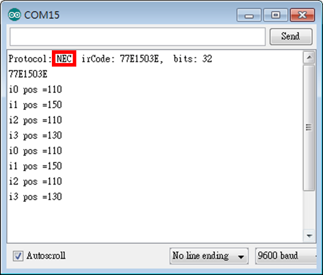
    程式的執行畫面為:


    Lab6_3_3:不知是何姓名版
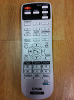
    基於Lab6_3_2需要相互「速配」才能蹦出火花(在Arduino IDE的串列顯示器上僅會顯示Unknown encoding),我們找了Epson投影机搖控器來測試,程式修改處如粉紅色标示處,我們拿到了遙控器识別的副程式showIRProtocol(),並逐一將按鍵的內碼填到方向控制的switch选項內(例如:0xC1AA09F6表示前進)。


    程式碼:
    #include <Servo.h>
    #include <SoftwareSerial.h>
    #include <IRremote.h>

    const int irReceiverPin = 2; //紅外線接收器輸入訊號接在Arduino第2腳
    IRrecv irrecv(irReceiverPin); //宣告IRrecv物件來接收紅外線訊號
    decode_results results;

    Servo servo_0, servo_1, servo_2, servo_3;

    int i0 = 110;
    int i1 = 150;
    int i2 = 110;
    int i3 = 130;
    int i0max = 180;
    int i0min = 0;
    int i1max = 180;
    int i1min = 90;
    int i2max = 150;
    int i2min = 50;
    int i3max = 160;
    int i3min = 100;

    void setup() {
      Serial.begin(9600);
      irrecv.enableIRIn();
      delay(100);

      servo_0.attach(11); //buttom
      servo_0.write(i0);

      servo_1.attach(10); //right(面对爪子)
      servo_1.write(i1);

      servo_2.attach(9); //left
      servo_2.write(i2);

      servo_3.attach(5); //claw
      servo_3.write(i3);

      delay(100);
    } //end of setup()

    void loop() {
      if (irrecv.decode(&results)) {
        Serial.print("Key code=");
        Serial.println(results.value, HEX);
       
        switch (results.value) {
          case 0xC1AA09F6: //前進
            Serial.println("0xC1AA09F6:forward");

            if (i2 < i2max) i2++;
            break;
          case 0x38863BC4: //左轉
            Serial.println("0x2D0:turn left");

            if (i0 > i0min) i0++;
            break;
          case 0x38863BE4: //右轉
            Serial.println("0xCD0:turn right");

            if (i0 > i0min) i0--;
            break;
           case 0x38863BC8: //後退
            Serial.println("0xAF0:back");

            if (i2 >= i2min) i2--;
            break;
          case 0x38863BE8: //上移
            Serial.println("0x90:up");

            if (i1 < i1max) i1++;
            break;
           case 0x38863BD8: //下移
            Serial.println("0x890:down");

            if (i1 > i1min) i1--;
            break;
          case 0x38863BE0: //夾緊
            Serial.println("0x490:tight");

            if (i3 < i3max) i3++;
            break;
          case 0x38863BD0: //放鬆
            Serial.println("0xC90:loose");

            if (i3 > i3min) i3--;
            break;
        }//end of switch

        irrecv.resume(); //Receive the next value

        servo_0.write(i0);
        servo_1.write(i1);
        servo_2.write(i2);
        servo_3.write(i3);

        Serial.print("i0 pos =");
        Serial.println(i0);
        Serial.print("i1 pos =");
        Serial.println(i1);
        Serial.print("i2 pos =");
        Serial.println(i2);
        Serial.print("i3 pos =");
        Serial.println(i3);
        delay(10);

        Serial.flush();
      } //end of if
    } //end of loop()


    執行結果:
    Key code=C1AA09F6
    0xC1AA09F6:forward
    i0 pos =110
    i1 pos =150
    i2 pos =110
    3 pos =130
    Key code=C1AA31CE
    i0 pos =110
    i1 pos =150
    i2 pos =110
    i3 pos =130
    Key code=C1AA29D6
    i0 pos =110
    i1 pos =150
    i2 pos =110
    i3 pos =130
    Key code=C1AA0EF1
    i0 pos =110
    i1 pos =150
    i2 pos =110
    i3 pos =130
    Key code=C1AA6E91
    i0 pos =110
    i1 pos =150
    i2 pos =110
    i3 pos =130
    Key code=C1AA2ED1
    i0 pos =110
    i1 pos =150
    i2 pos =110
    i3 pos =130
    Key code=C1AAFC03
    i0 pos =110
    i1 pos =150
    i2 pos =110
    i3 pos =130
    Key code=C1AAC23D
    i0 pos =110
    i1 pos =150
    i2 pos =110
    i3 pos =130

    参考資料:
    1. Arduino練習:紅外線傳送與接收,葉難,http://yehnan.blogspot.tw/2013/05/arduino.html。
    2. A Multi-Protocol Infrared Remote Library for the Arduino,Ken Shirriff,http://www.righto.com/2009/08/multi-protocol-infrared-remote-library.html.
    3. IRrecv Class,CY's Tech Talk,http://tech.cyborg5.com/irlib/docs/1-irlib-reference/1-1-receiver-classes/1-1-3-irrecv-class/.
    4. 六種授權條款,台灣創用CC計畫,http://creativecommons.tw/explore。